36. Lower Control Arms
|
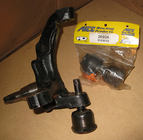
The picture shown here is a typical Mustang II/Pinto spindle with corresponding ball joints. The upper and lower screw-in ball joints are nearly identical to each other, readily available and not very expensive. These parts can be found in most race car catalogs, especially those who specialize in stock car and dirt track racing. |
|
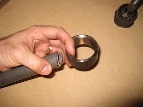 Step 2: Acquire a threaded ball-joint sleeve that matches the selected ball joints. Threaded ball joint sleeves are typically 1 inch high with an inner diameter to fit standard "screw-in" ball joints. There are two common sizes of threaded ball joint sleeves, creatively referred to as "large" and "small". Upper ball joints typically use a "small" ball joint sleeve. I see no reason why you couldn't use this style of upper ball joint on both the top and bottom as long as the taper matches your spindle and the castle nut properly seats. Step 2: Acquire a threaded ball-joint sleeve that matches the selected ball joints. Threaded ball joint sleeves are typically 1 inch high with an inner diameter to fit standard "screw-in" ball joints. There are two common sizes of threaded ball joint sleeves, creatively referred to as "large" and "small". Upper ball joints typically use a "small" ball joint sleeve. I see no reason why you couldn't use this style of upper ball joint on both the top and bottom as long as the taper matches your spindle and the castle nut properly seats. |
|
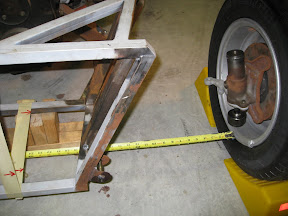 Step 3: With the wheels and tires that you plan to use in your final assembly, insert the lower ball joint into the threaded sleeve. Mount the lower ball joint to the spindle. Mount the spindle to your front hub. Mount the hub to the wheel. Support the chassis at static ride height (typically 5 or 6 inches from the ground). Measure the track width of the rear end by placing a tape measure between the inside of the rear wheels. Divide this measure in half. Note the centerline of the chassis at the front end. Position the front wheel assembly where it will rest when the car is fully assembled based on "half the track width". It may seem awkward to "float" the tire/wheel/upright/ball joint assembly in the middle of thin air, but you'll quickly see how this is an efficient way to determine the lower control arm geometry for nearly any combination of donor parts. Positioning the front wheel assembly slightly wider that the rear is generally acceptable and may even be preferred. A front track width that is less than the rear is generally undesirable. Step 3: With the wheels and tires that you plan to use in your final assembly, insert the lower ball joint into the threaded sleeve. Mount the lower ball joint to the spindle. Mount the spindle to your front hub. Mount the hub to the wheel. Support the chassis at static ride height (typically 5 or 6 inches from the ground). Measure the track width of the rear end by placing a tape measure between the inside of the rear wheels. Divide this measure in half. Note the centerline of the chassis at the front end. Position the front wheel assembly where it will rest when the car is fully assembled based on "half the track width". It may seem awkward to "float" the tire/wheel/upright/ball joint assembly in the middle of thin air, but you'll quickly see how this is an efficient way to determine the lower control arm geometry for nearly any combination of donor parts. Positioning the front wheel assembly slightly wider that the rear is generally acceptable and may even be preferred. A front track width that is less than the rear is generally undesirable. |
|
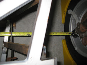 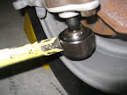 Step 4: Having mounted at least one of the lower control arm brackets on the chassis (the forward most bracket is best for this operation), insert a threaded rod, wooden dowel, or something similiar through the bracket to represent the lower control arm pivot point (or just "eye-ball it"... within 1/4" is good enough). Measure the distance between the center of the threaded rod and the outer diameter (OD) of the ball joint sleeve. Step 4: Having mounted at least one of the lower control arm brackets on the chassis (the forward most bracket is best for this operation), insert a threaded rod, wooden dowel, or something similiar through the bracket to represent the lower control arm pivot point (or just "eye-ball it"... within 1/4" is good enough). Measure the distance between the center of the threaded rod and the outer diameter (OD) of the ball joint sleeve. This measure can vary greatly depending on the rear track width of your donor, the design of your chassis, your selection of uprights, wheels, and/or wheel offset spacers. I'm often asked if I have any suspension plans to go along with the McSorley 442. The best answer I can provide is to follow the process that I've described here, and get this measure "pretty close" to where you want to be for the front track width. Then follow along with the rest of my build and you'll see how it all comes together... adjustability is the key. You will see later how this "generic" solution will work on your build too... without the need for any drawings or plans. |
|
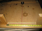  Step 5: Create a simple jig made of plywood with a back stop for the ball joint sleeve and a line drawn down the middle. Transfer the measure from step 4 to the jig. Draw another line perpedicular to the first, representing the centerline of the lower control arm pivot points, based on the measure that you just transferred over. Measure 7 inches to each side of the intersection of the two lines along the line representing the lower pivot point. This will define a control arm spread of 14 inches total. Mount some kind of stop blocks (in this case, 2x4 wood scraps) to the outside of the 14 inch spread. Step 5: Create a simple jig made of plywood with a back stop for the ball joint sleeve and a line drawn down the middle. Transfer the measure from step 4 to the jig. Draw another line perpedicular to the first, representing the centerline of the lower control arm pivot points, based on the measure that you just transferred over. Measure 7 inches to each side of the intersection of the two lines along the line representing the lower pivot point. This will define a control arm spread of 14 inches total. Mount some kind of stop blocks (in this case, 2x4 wood scraps) to the outside of the 14 inch spread. |
|
|
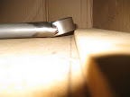
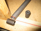
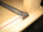
Step 6: Recognizing that the diameter of a typical bench-top belt sander is nearly the same as a threaded ball joint sleeve, grind a "fish-mouth" on the end of the DOM tubing to create the left and right segments of the lower control arm. I used a 40 grit sanding belt, which was the most agressive grit I could find. Be sure to use a thick-walled (.125" or greater), drawn-over-mandrel (DOM), cold-rolled steel tube for this application. I decided to not use 4130 chromoly because it costs more, it is harder to machine, and I don't have any experience welding 4130 to the common steel of the threaded ball joint sleeve. I've been told that there is no problem doing so... I just didn't see the need for this application. |
|
|
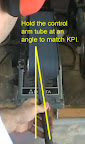
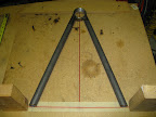
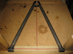
Creating a proper jig seamed unnecessary to me... I held these parts with a gloved hand and tack welded them together "in mid air." The free ends of the tubes were held the correct distance apart by tying them to the stop blocks (14 inches apart). I even used the width of my own hips to keep these tubes properly spread (pushing into the stop blocks) while tack welding. It is not a perfect science. Holding the parts by hand allowed me to bias the tubes toward the top of the sleeve, keeping everything flush along the bottom. We need to be sure that the ball joint fully threads into the ball joint sleeve when we're done. Any extra welding material along the bottom might not allow the ball joint to fully seat. Be sure to weld no more than 1 inch at a time. Allow the ball joint sleeve to cool between welds. It is easy to distort the threads with too much heat... you don't have to ask why I know that... you can take a wild guess. Lastly, be sure to use Anti-Sieze when screwing the ball joints into the sleeves... they tend to cross-thread quickly and any dirt in the assembly (even surfaced carbon from the welding process) will cause everything to bind easily. |
|
    |
|
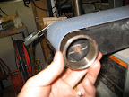
| The design of the bushing tubes shown here was taken directly from Ron Champion's book. The bushings are sourced from a Spitfire front suspension. The bushing tubes are fabricated from 1" OD, .095" wall common steel tubing. The length of the bushing tubes is 1.4 inches. A process for press-fitting these bushings into the bushing tube can be seen in a previous assembly article for the rear trailing arms. I recommend a piece of wooden dowel with a 3/8" hole to simulate the rubber bushings during trial assembly... it is not practical to remove the rubber bushings if you plan to powder coat the lower control arm later on. |
|