37. Upper Control Arms
|
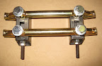
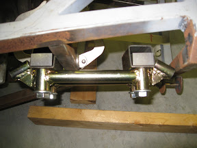
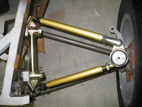
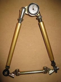
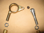
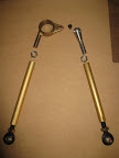
On the other end of the assembly is a purpose-built "control arm cross member". The cross member has two mounting tubes, placed exactly 6 inches apart on center. Both ends of the cross member hold left-hand threaded rod-ends. The rod-ends are bolted in single sheer to threaded tubes that are welded in place at roughly 45 degrees. The weld penetration and finish quality of the cross member is exceptional... this is a piece that I would not be comfortable making at home.
Connecting the ball joint carrier with the rod ends are threaded tubes with opposing threads on each end. Some vendors provide steel swedged tubing with 5/8" right hand thread on one end, and 1/2" left hand thread on the other. I decided to use aluminum tubing of constant diameter (not swedged) having opposite 5/8" threads on each end. This approach required the purchase of 1/2" rod ends with 5/8" threads to match the threaded tubing. The complete assembly option comes with the more typical 1/2" rod end with 1/2" thread as a complete "kit," but you may have to purchase longer swedged tubing to fit your particular need. The threaded control arm tubes for my build are 9 inches in length, or roughly half the length of the lower control arms overall. All of these components are commonly used on race cars that run hundreds of laps in a given race, at speeds well over 100 miles per hour, so I have little concern regarding the strength or longevity of this solution. |
|
|
|
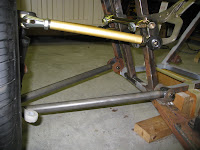
Positioning the lower cross member about 7 inches away from the lower pivot point causes the cross member in the upper position to be about 9 inches away. This approach "splits the difference," providing 1 inch of up-and-down adjustability relative to the "recommended" position of the book's upper control arm pivot point. Two inches of adjustability in the positioning of the upper cross member results in a range of at least 10 degrees in the downward angle of the upper control arm as it approaches the chassis... enough flexibility for nearly any design. As a general starting point when dramatically deviating from the book (assuming the lower control arm is level to the ground), you should place the middle of the slider box at some distance from the lower control arm pivot point such that the upper control arm sits at a roughly 13 degrees downward angle (from a front view) as it appraoches the chassis. This is just a rough guideline, knowing that you will be able to adjust the upper control arm pivot point and shift the angular difference between the upper and lower control arms by at least 5 degrees in either direction later on. |
|
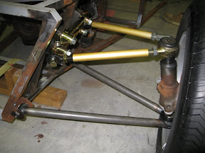
If I had the opportunity to redesign the chassis from scratch, I would forego the forward-most upright of the book design (LA & LB) in favor of this new vertically oriented and parallel upright approach. I find the compound angles of the book design to be overly difficult to fabricate and even more restrictive when it comes to choosing a mounting point for the upper control arms. Using the approach shown here, there is no need to choose an exact position for the upper control arm pivot point during the chassis build. The selection of an inner pivot point is something that can be done later in the build, or at anytime down the road. You could even "fine tune" the front suspension geometry after installing a different wheel or tire diameter (or even different uprights!) much later in the build process... all without having to reweld any brackets, etc. |
|
|
| I spent many hours deliberating over the geometry of my front suspension because I wanted everything to be "just right." In reality, the front end of of my hand-built chassis is off by at least 1/4" from side to side, and nothing is ever going to be perfect. I was determined to use an adjustable upper control arm, so the standard brackets specified by the book simply would not work. In general, this is a known challenge when using rod-ends for the upper control arm, a problem that is nicely documented and solved by Kinetic Vehicles with their angled brackets. While I could have easily used the Kinetic approach, I did not want to spend any more time thinking about the ideal placement of the inner upper pivot points. Using the approach shown here, an adjustable upper control arm was combined with adjustable mounting points, offering a highly flexible design and an unsurpassed level of adjustability.
As a closing note, I am frequently asked if I can provide drawings for a suspension design to compliment the drawings provided on this website. The short answer is, "sorry, no." The reason is because I have no knowledge of the geometry defined by your donor parts (wheels, uprights, etc.) and more importantly, I couldn't possibly come up with every geometric combination that you might want to explore. I hope you agree that the process shown here is flexible enough to accomodate nearly any combination of donor parts, proving that a practical supension design for a hand-built car is not about custom geometry, but rather... ensuring adjustability so that you can tune the solution to your particular need. |
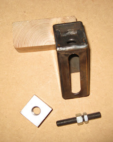
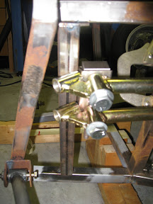
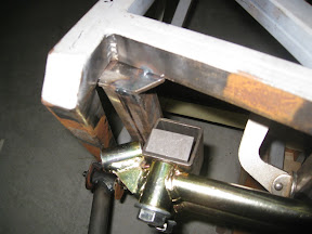
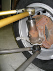
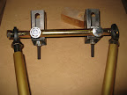 The control arm cross member will be mounted to the chassis using 1/2" bolts and lock washers. Each bolt will be threaded into a square plug that is strategically placed inside the slotted component shown here on the right. During installation, the square plug can slide up and down the slot in this welded box a full 2 inches, providing adjustability of the upper control arm inner pivot point. A small threaded rod that is similiar to a set screw (sometimes called a "jack screw" in this case) is inserted into the bottom of the slider box as a way to fine tune the adjustments. Adjustability is what separates this solution from the book design. This adjustability accomodates nearly any donor parts since you don't have to specify the exact position of the upper control arm pivot points during chassis construction.